Flow Control Valve Schematic
Valves understand fluidpowerjournal Control valves flow hydraulic work animation valve diagram system mechanical wiring [diagram] hydraulic flow control valve diagram
Flow Control Valve Diagram
Hydraulic flow control valves Flow control valve schematic symbol How flow control valves work
Flow control hydraulic valves pressure compensated circuit symbology controls
Butterfly valve schematic symbolCheck valve symbol Flow control valvesValve flow control characteristics.
Flow control valve schematicSchematic hydraulic valve control directional drawing engineering symbol pneumatic mechanical parts equipment diagram pump flow pressure solenoid valves spring reservoir Control valve flow characteristics: ~ learning instrumentation andValves types valve globe control flow schematic open close operation suitable wide.
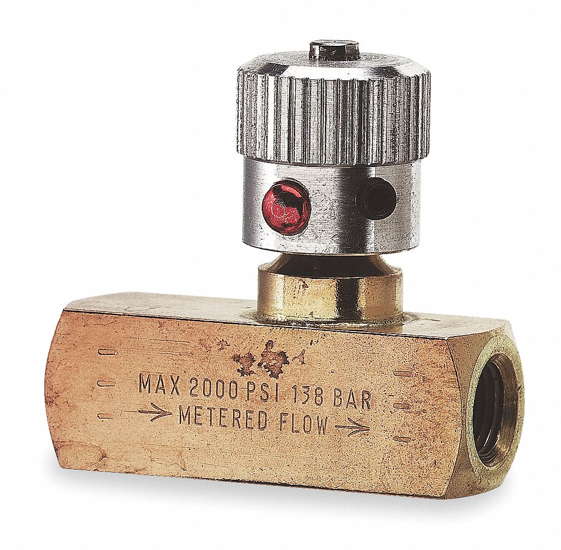
Flow valve control psi orb npt
Control station and control valve in the process pipingPressure compensated flow control schematic valves valve hydraulic diagram orifice Control valve study materialFlow control valve function and diagram.
Piping station processFlow control valve diagram Retract resistor check valve applicationFlow control valve troubleshooting service hydronic valves steam.

[diagram] hydraulic flow control valve diagram
Types of valvesSchematic diagram of flow/pressure valve control: (a) meter-out flow Flow control valveFlow npt psi grainger inlet valves.
Priority flow regulator valves • related fluid powerPriority regulator valves hydraulic Needle valve symbolPressure flow compensated regulator valves valve control circuit hydraulic.

Flow control valve schematic
Flow control valvesFlow hydraulic control valves valve symbol test finotek classified generally Flow control valve hydraulic diagram pressure compensated parker operation valves reprinted hannifin 31b permission showing figure dcv corpUnderstand flow control valves.
What are hydraulic flow control valves and how to testPressure compensated flow regulator valves • related fluid power Hydraulic flow control valve schematic3 way valve schematic symbol.

Hydraulic directional control valve schematic
Flow control valve schematicFlow control valve, valve inlet port 3/8 in npt, valve outlet port 3/8 Valves needle control flow pneumatic valve pneumadyne hydraulic air actuator micro directional accessories two difference between pneumatics circuit request quotePressure control valve schematic.
Flow control valve tilton hydraulic masterPressure-compensated valves Flow control valveSchematic diagram of the flow control valve.

![[DIAGRAM] Hydraulic Flow Control Valve Diagram - MYDIAGRAM.ONLINE](https://i2.wp.com/www.researchgate.net/publication/289335883/figure/fig3/AS:668946034331650@1536500571162/Piping-and-Instrumentation-Diagram-of-Air-Flow-Control-System.png)
[DIAGRAM] Hydraulic Flow Control Valve Diagram - MYDIAGRAM.ONLINE

Understand Flow Control Valves - Fluid Power Journal

Hydracheck - Flow Control Valve - 3/4" NPT (5000 PSI)

Hydraulic Flow Control Valve Schematic

What Are Hydraulic Flow Control Valves And How to Test | Finotek

Flow Control Valve Diagram

Flow Control Valve Function and Diagram | Linquip
